|
|
| |
|
 | Search: |
|
|
 |
|
|
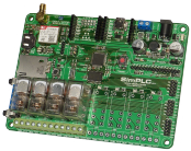
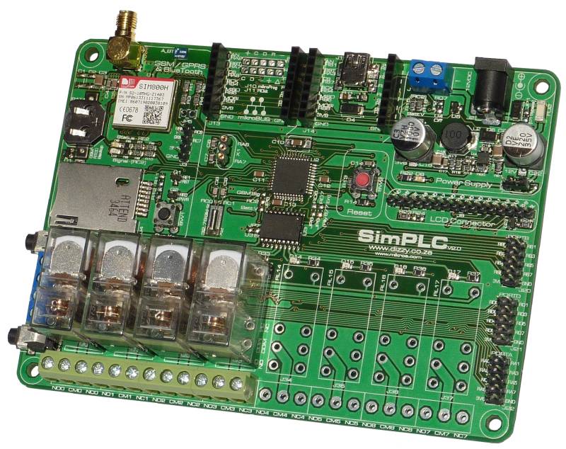
The SimPLCv2 is a neat and compact board featuring up to 8 relays, a GSM/GPRS/Bluetooth/FM-Radio module, up to 8 opto-coupled inputs, RTCC (real-time calendar/clock), USB and an LCD Connector. Develop your own code to turn it into an alarm system, remote control/monitoring device, or any other application you may find for it! |
|
|
|
|
 Features
-
Up to 8 Relays (4 included as standard).
- LED to indicate the state of each relay.
- Relays can be easily disabled via a jumper (LEDs still operational) during your development / debugging phase.
- SIM800H GSM / GPRS / Bluetooth / FM Radio Module.
- 3.5mm jack and screw-terminal microphone and speaker connectors.
- Power and signal LEDs.
- Header for debugging UART communications with the module.
- Pwr_Key button for manually powering the module on and off.
- Backup battery for RTCC (real-time calendar and clock).
- On-board 2.4GHz Bluetooth chip antenna.
- FM Radio uses speaker audio cable for antenna.
- MikroElektronika-standard IDC10 connectors for Ports A, B and D; as well as two "mikroBus" connectors, used to easily add functionality by connecting any of a huge range of accessory boards (see "Related Items").
- Up to 8 opto-coupled inputs by using OPTO click boards.
- PIC18F47J53 microcontroller.
- 32.768kHz crystal included on-board, for running the PICs built-in RTCC (real-time calendar/clock).
- USB.
- mikroProg and PICkit programmer connectors.
- Comes pre-programmed with a fast USB-HID bootloader.
- Reset button.
- Switching power supply.
- Switches the 12V input voltage down to 3.6V.
- Input voltage readable by the MCU (for battery monitoring).
- DC-DC converter can be shut down during standby for minimal power consumption.
- Board can be powered via USB during your development / debugging phase (relays should be disabled via the "Relay En" jumper).
- Alphanumeric LCD Connector.
Example Programs
Example programs are included with the board, helping you to get up and running with your project quickly.
These included examples programs demonstrating how to:
- Switch relays on and off.
- Read inputs.
- Work with the RTCC (real-time calendar and clock).
- Work with the GSM/GPRS module. A robust, tidy, flexible and easily extendable state-machine based GSM Library framework is provided, which already caters for:
- Switching the module on, setting it up, and waiting for network registration.
- Sending and receiving SMSs.
- Detecting and reacting to missed calls.
- Interacting with a web-server.
|
|


 Download User Manual (2MB)